TOOLING-LED. REPEAT-PRODUCTION READY.

Custom Die Casting
Services

Use die casting when the part and program justify a repeatable tooling route.

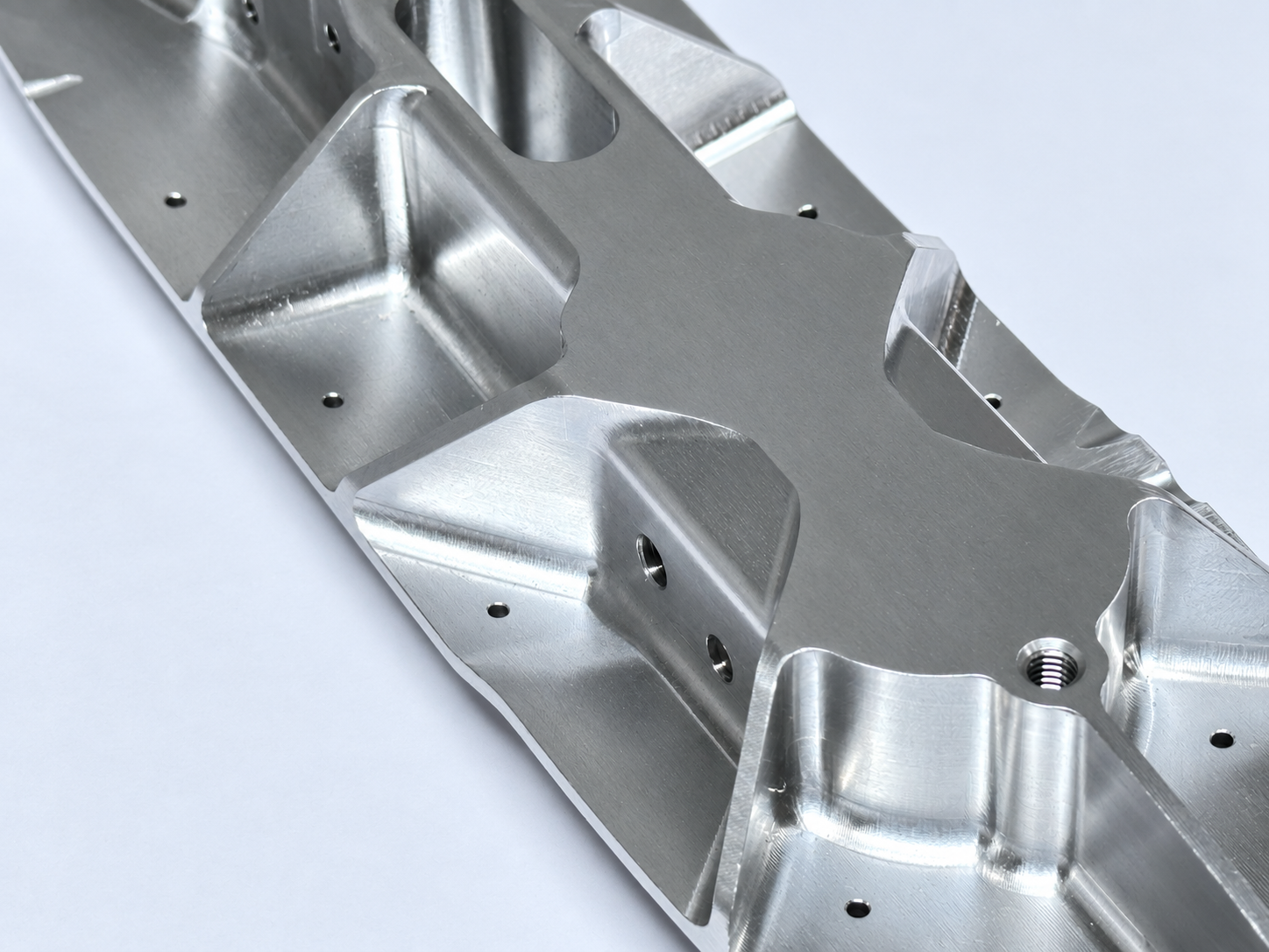
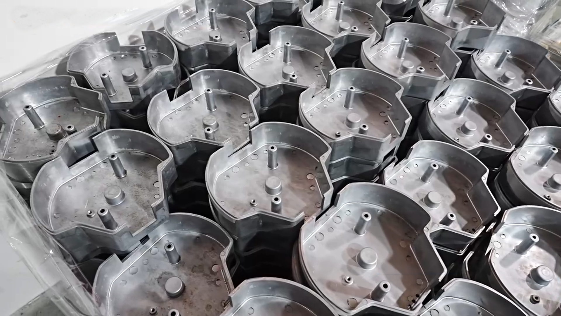
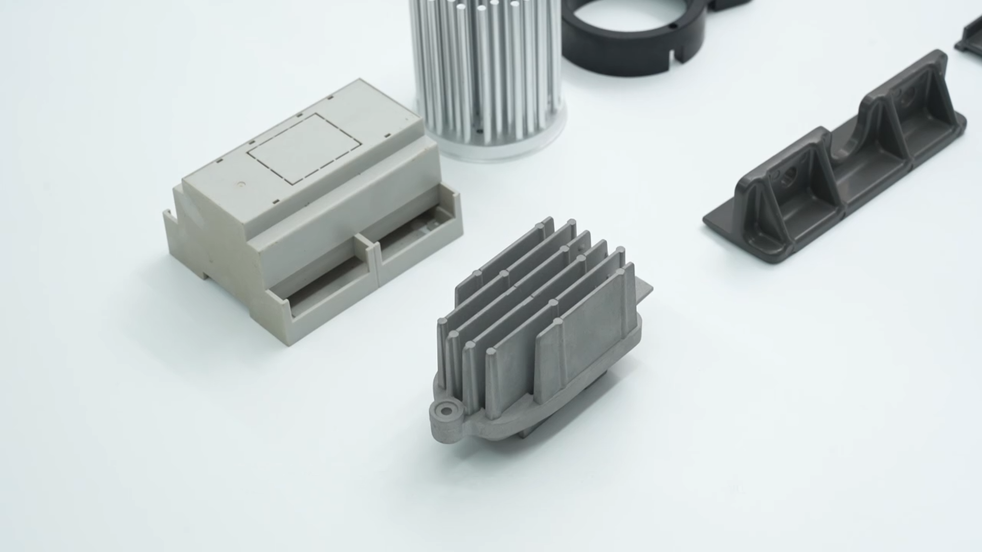
Die casting is considered for repeat-production aluminum or zinc parts where tooling can support the required geometry and volume. The drawing review focuses on draft, wall consistency, ribs, bosses, parting lines, ejector locations, functional interfaces and the surfaces that may need secondary CNC machining. Cast surfaces and machined interfaces are planned separately so the part meets its functional and appearance requirements.

Drawing Review Material & Finish Options Production Coordination
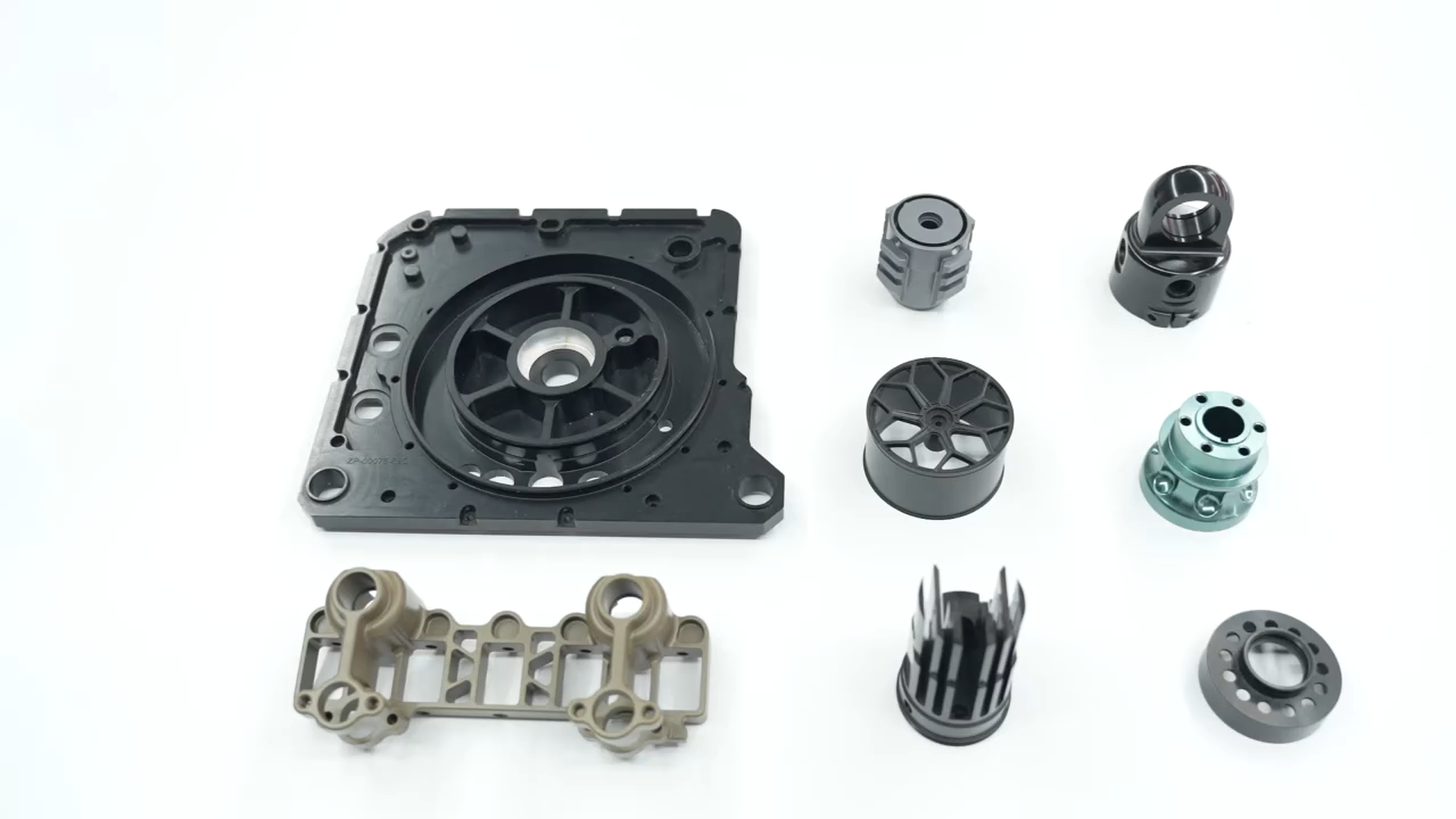
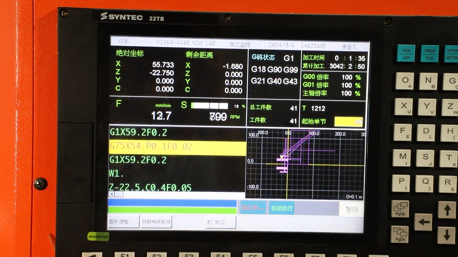
Die Casting production equipment and componentsFrom Your Drawing
to Real Parts

MATERIAL OPTIONS

Choose the Right
Material for Your Part.

Aluminum and zinc alloy are reviewed with castability, feature detail, functional interfaces, appearance requirements, secondary machining and finish. Alloy selection is part of the tooling and geometry decision, not a separate afterthought.

Aluminum Alloy material referenceMaterial guide

SELECTED MATERIAL

Aluminum Alloy

Review cast geometry, functional interfaces, finish compatibility and secondary machining together for repeat-production parts.

Common Grades
ADC12, A380, ADC10, A383, A413
Key Characteristics
Lightweight Β· Castable Β· Dimensionally stable
Typical Applications
Housings, heat-management and electronic assemblies
Available Finishes
As cast, machining, powder coating, painting
Discuss your material choice β†’

SURFACE FINISHES

The Finish That
Fits Your Application.

Separate as-cast surfaces from critical holes, threads, bores, mounting faces and other interfaces that may need secondary CNC machining. Identify visible faces, finish requirements and masking needs before the route is fixed.

01

As Cast

A cost-efficient finish retaining the cast surface for non-cosmetic or internal features.

View More
02

Powder Coating

A durable colored coating for cast housings and exterior components.

View More
03

Painting

A flexible color finish for visual requirements and controlled surface coverage.

View More
04

Electroplating

A metallic plated layer for added corrosion resistance or appearance.

View More
05

Sandblasting

A uniform matte texture that prepares surfaces and reduces visible marks.

View More
06

Machining

Secondary machining for critical holes, threads and assembly interfaces.

View More

BUILT FOR A WIDE RANGE OF INDUSTRIES

Die Casting
for Real-World Applications

Suitable for repeat-production housings, covers, handles and detailed components where a tooling route can be evaluated against alloy, quantity, geometry, secondary-machining needs and functional surfaces.

Explore All Applications β†’
Automotive precision manufacturing

Automotive

Repeatable housings, covers and thermal-management components

Aerospace precision manufacturing

Aerospace

Program-specific lightweight cast equipment components

Medical Devices precision manufacturing

Medical Devices

Equipment housings, handles and durable device components

Communication precision manufacturing

Communication

Detailed RF, network and heat-management housings

Energy precision manufacturing

Energy

Electrical enclosures and durable power-system components

Marine Vessel precision manufacturing

Marine Vessel

Detailed housings and hardware for corrosion-conscious assemblies

BUILT FOR DEMANDING PROJECTS

Inputs That Shape a
Casting Program

The review distinguishes the features that can be cast from the interfaces that should be machined or controlled after casting.

01

Tooling Dependency

Repeat-production value depends on the approved part, alloy, quantity and tooling assumptions; no universal production threshold is published.

02

Cast Geometry

Draft, wall consistency, ribs, bosses, parting lines and ejector locations are reviewed together for a practical die-casting route.

03

Functional Surfaces

Identify critical holes, threads, bores, mounting faces and sealing or assembly interfaces that may need secondary machining.

04

Alloy & Finish

State whether aluminum or zinc alloy is preferred, then define as-cast, machined and cosmetic surfaces separately.

05

Inspection Scope

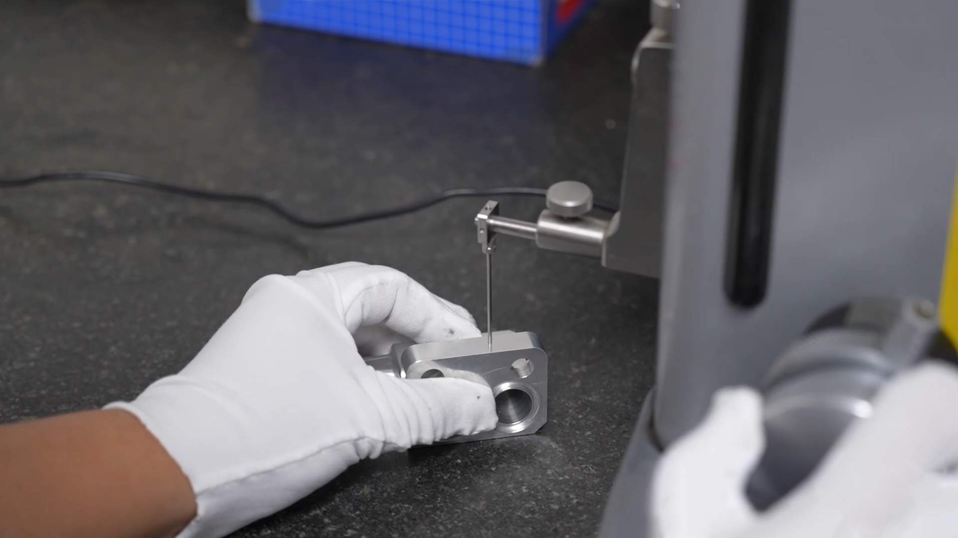
Call out critical dimensions, first-article needs, CMM requirements where applicable and any agreed documentation.

Real die casting production reference

A CLEARER PATH TO YOUR PARTS

From Drawing to Delivery

The process review connects tooling assumptions to cast geometry, secondary machining, finish and drawing-defined inspection instead of treating the cast part as a finished part by default.

01

Send Drawings

Provide the 2D/3D drawing, preferred aluminum or zinc alloy, expected quantity, critical dimensions, secondary-machining needs, finish, delivery target and inspection requirements.

02

DFM Review

Review draft, wall consistency, ribs, bosses, parting lines, ejector locations, functional surfaces and any required secondary CNC machining.

03

Die Casting

Plan tooling assumptions, casting and secondary operations around the approved alloy, geometry and the distinction between cast and machined surfaces.

04

Quality Inspection

Check drawing-defined cast geometry and critical machined interfaces. CMM inspection can be used where appropriate to the project; requirements are agreed before production.

05

Delivery Planning

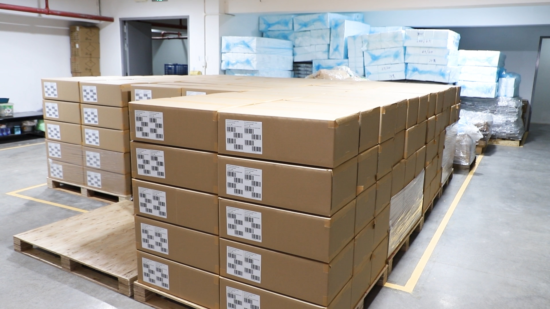
Plan samples, production and shipment from the approved drawing, alloy, quantity, finish and agreed delivery terms.
QUALITY ASSURANCE

Quality Built In.
Confidence Delivered.

Inspection is planned around the cast geometry, machined features, functional interfaces and cosmetic requirements defined for the finished part.

Our Quality Process β†’
  • Drawing Requirement Review
  • Material Verification
  • Surface & Appearance Check
  • Process Documentation
ItemSpecification
Cast & machined featuresDrawing-defined cast geometry and critical machined interfaces are checked against agreed specifications; CMM inspection can be used where appropriate to the project.
Inspection ApproachProcess-appropriate visual, dimensional and functional checks.
Inspection StandardsBased on customer drawings and agreed specifications.
DocumentationInspection information and material documentation available when specified.
Quality PlanningRequirements reviewed before production and monitored through delivery.

FROM PROTOTYPE TO PRODUCTION

Flexible Volumes.
Consistent Quality.

A tooling-backed route is evaluated for repeat projects. A typical starting quantity is 1,000 pcs, subject to the approved part, alloy, tooling assumptions and order requirements; samples are typically 15–30 days.

Sample Development manufacturing at T-One

Sample Development

Samples are typically 15–30 days, subject to the approved design, alloy, tooling and project requirements

Repeat Production Review manufacturing at T-One

Repeat Production Review

Evaluate tooling assumptions, quantity, secondary machining, finish and inspection scope before scheduling

Order Planning manufacturing at T-One

Order Planning

Production timing depends on quantity and the agreed project scope; tooling lead time is established during quotation

FREQUENTLY ASKED QUESTIONS

Your Questions, Answered.

READY TO START?

Upload Your Drawings.
Get a Quote.

Send the 2D/3D drawing with preferred aluminum or zinc alloy, expected quantity, critical dimensions, draft or wall constraints where known, secondary-machining needs, finish, first-article or inspection requirements and delivery target.

Get a Quote β†’
Die Casting Services for Custom Metal Parts | T-One