Laser Cutting
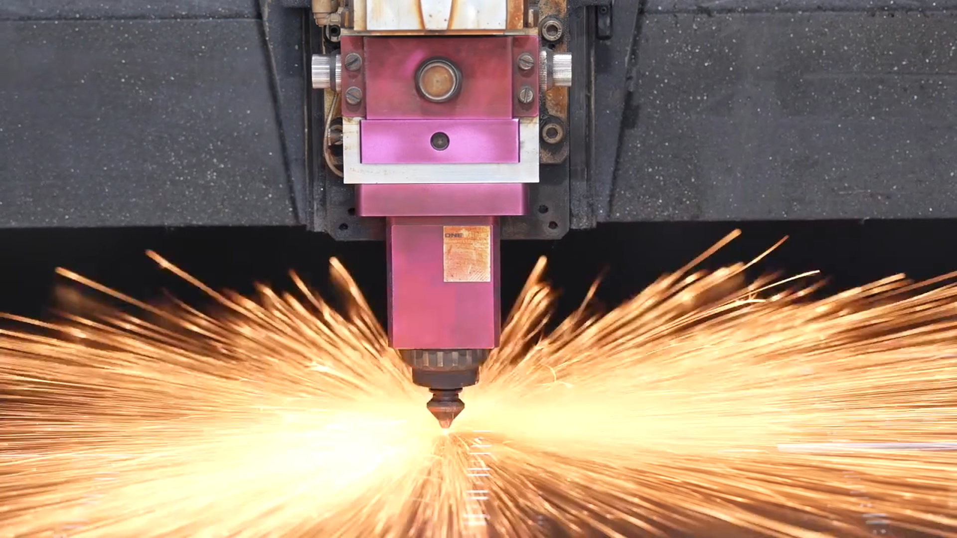
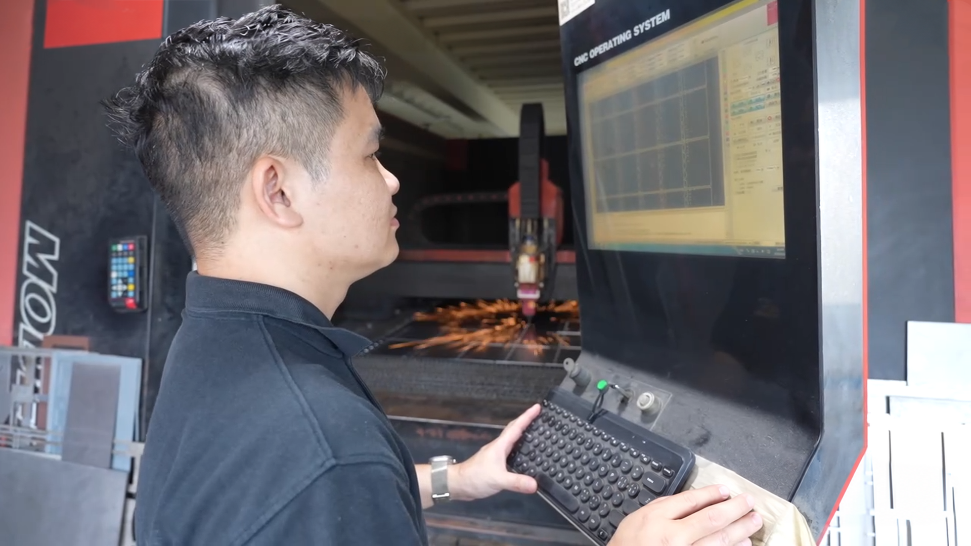
Profiles, holes, slots and cut-outs are reviewed from the flat pattern, including their clearance from bend lines and any downstream hardware or joining operation.
Explore service →
FLAT PATTERN TO FORMED PART.
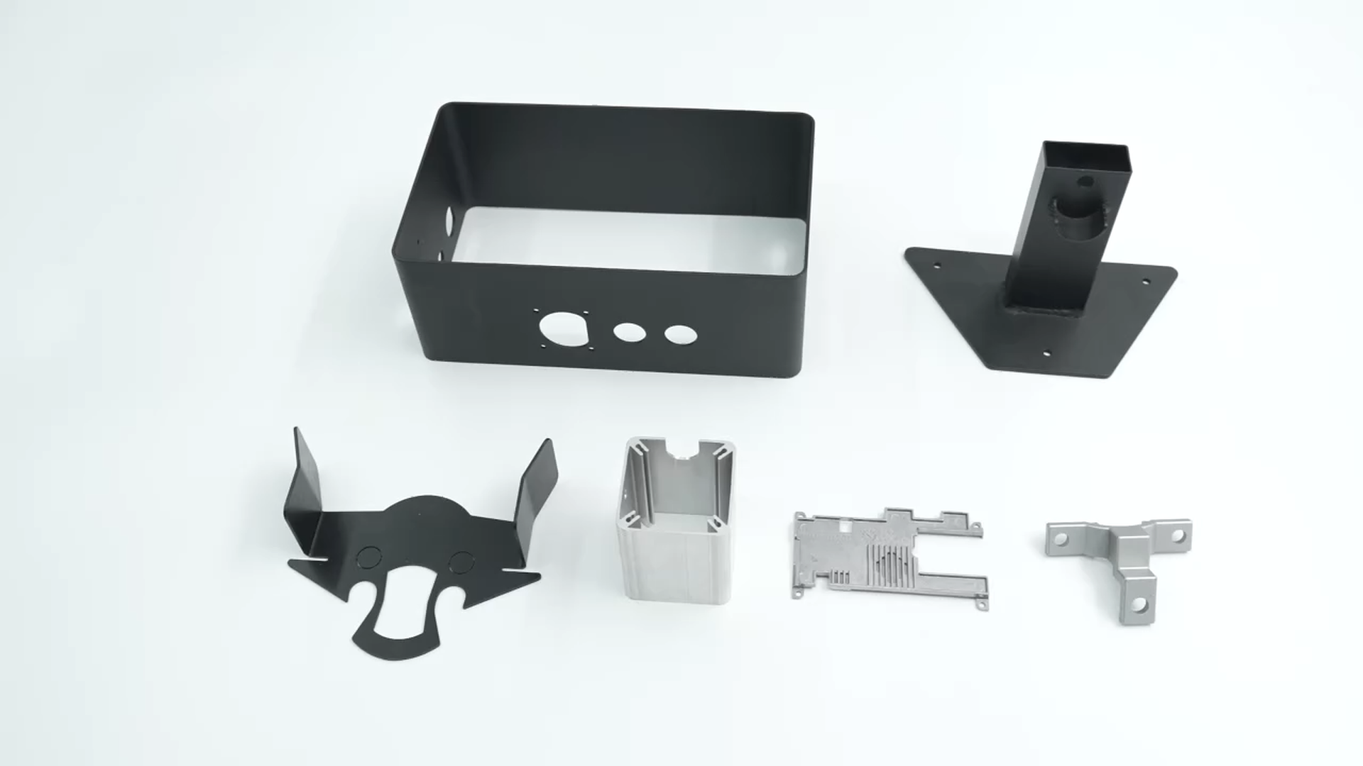
Sheet metal fabrication is suited to enclosures, panels, brackets and formed assemblies that begin as a flat pattern. We review material formability, thickness, bend sequence, holes or slots near bends, flanges, tabs, hardware and finish requirements before coordinating laser cutting, bending, joining and final assembly. Fiber laser sheets can be reviewed up to 2000 × 6000 mm; final feasibility depends on material, thickness, geometry and forming requirements.
 From Your Drawing
MANUFACTURING CAPABILITIES
A useful sheet-metal plan connects the flat pattern to the final formed part: cutting features must clear bends, flanges must allow tooling access, and hardware, joining and finish must be sequenced around functional and cosmetic surfaces.
Our Full Capabilities →Profiles, holes, slots and cut-outs are reviewed from the flat pattern, including their clearance from bend lines and any downstream hardware or joining operation.
Explore service →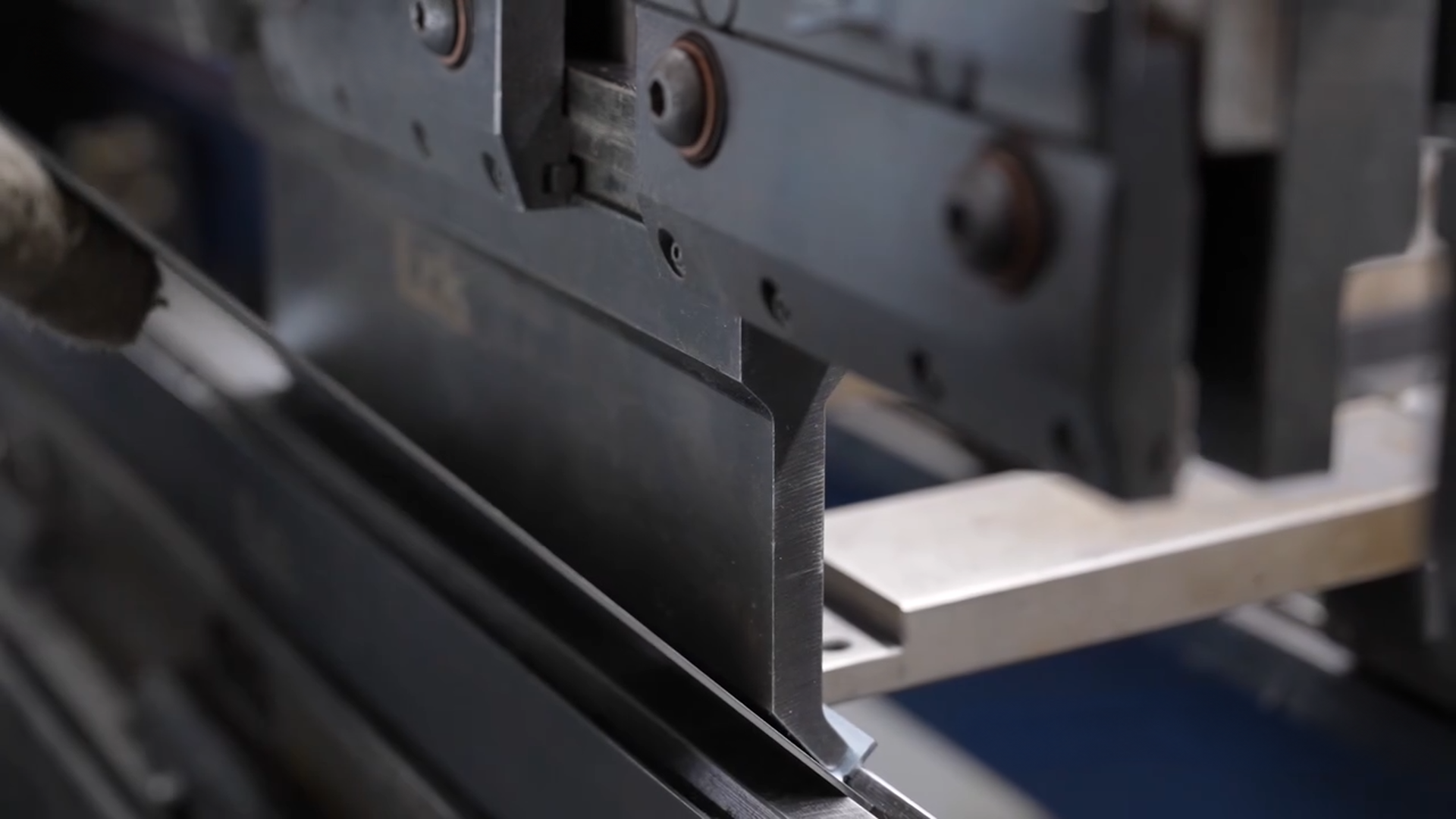
Press-brake work can be reviewed up to 320 ton, 3200 mm length and 10 mm maximum thickness, subject to material, geometry and the required bend sequence. No fixed bend-angle tolerance is published.
Explore service →MATERIAL OPTIONS
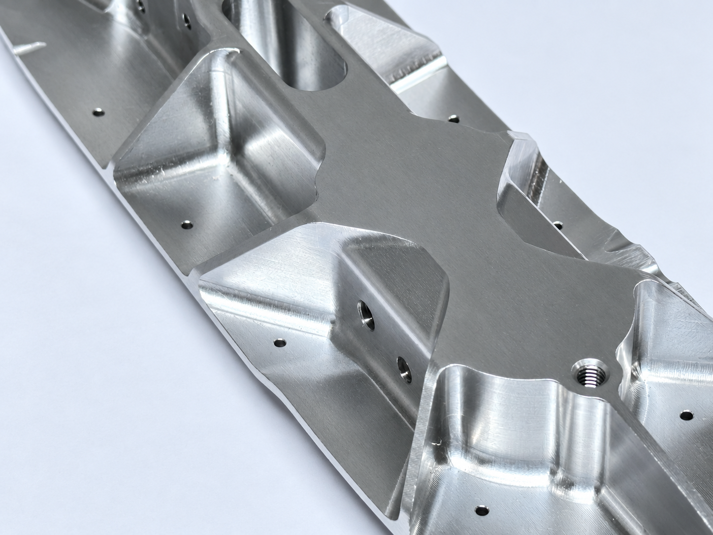
For sheet parts, material choice, thickness and formability are reviewed with bend sequence, joining, finish and the functional or cosmetic role of each face. A material is not selected independently from the formed geometry.
 Material guide
SELECTED MATERIAL
Review grade, thickness and bend direction together where low mass, corrosion resistance and formed geometry matter.
SURFACE FINISHES
Select the finish after identifying visible faces, mating areas, grounding or contact zones, hardware locations, masking needs and surfaces that must remain suitable for forming or assembly.
Review coverage, masking and cosmetic surfaces with the formed part and its assembly interfaces.
View MorePlan visual targets, coverage and protected surfaces alongside the formed-part sequence.
View MoreReview aluminum grade, critical interfaces and masking before finishing formed components.
View MoreA directional texture for visible sheet surfaces where grain direction should be specified.
View MoreA stainless-steel treatment route reviewed with material, exposure and post-fabrication handling.
View MoreA metallic finish route for compatible sheet materials where functional or appearance requirements are defined.
View MoreBUILT FOR A WIDE RANGE OF INDUSTRIES
Suitable for enclosures, panels, brackets, covers and formed assemblies that begin as a flat pattern. The manufacturing question is whether cutting, bending, hardware, joining and finish can be sequenced around the part’s functional and cosmetic requirements.
Explore All Applications →
Formed panels, brackets, covers and equipment housings

Lightweight panels, brackets and ground-support equipment parts
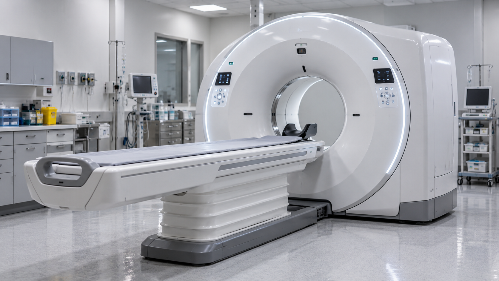
Equipment covers, cabinets and fabricated support components

Racks, chassis, cabinets and protective equipment enclosures

Control cabinets, panels and structural equipment covers

Formed cabinets, brackets and protective onboard enclosures
BUILT FOR DEMANDING PROJECTS
A useful review connects the drawing’s flat pattern to the final formed assembly, rather than treating cutting, bending and finish as separate decisions.
Provide the profile, material, thickness, holes, slots and cut-outs so features can be reviewed before forming.
Identify bend lines, flanges, tabs and hems where relevant; holes or slots near bends need review for formed-part clearance.
Call out PEM hardware, tapping, riveting, welding, spot welding or assembly needs so their sequence can be planned.
Separate cosmetic faces from functional, contact or protected areas and identify masking or grain-direction requirements.
Define formed dimensions, hardware locations, functional interfaces and appearance requirements that control acceptance.
A CLEARER PATH TO YOUR PARTS
The route is planned from flat pattern through cutting, bending, joining, hardware and finish so downstream steps do not compromise the formed part.
Provide the flat pattern or 3D model, material, thickness, quantity, bend details, hardware or joining needs, finish, delivery target and inspection requirements.
Review bend lines, flange access, holes or slots near bends, tabs, hems where relevant, hardware, joining sequence and cosmetic surfaces.
Coordinate laser cutting, bending, hardware insertion, welding, riveting, tapping, spot welding, deburring or assembly where the drawing requires them.
Check drawing-defined cut profiles, bend locations, formed dimensions, hardware, functional interfaces and agreed appearance requirements.
Plan production and shipping from the approved drawing, material availability, finish route, quantity and agreed delivery terms.
QUALITY ASSURANCE
Inspection is planned around the flat pattern, bend sequence, formed dimensions, hardware, functional interfaces and appearance requirements that matter to the assembly.
Our Quality Process →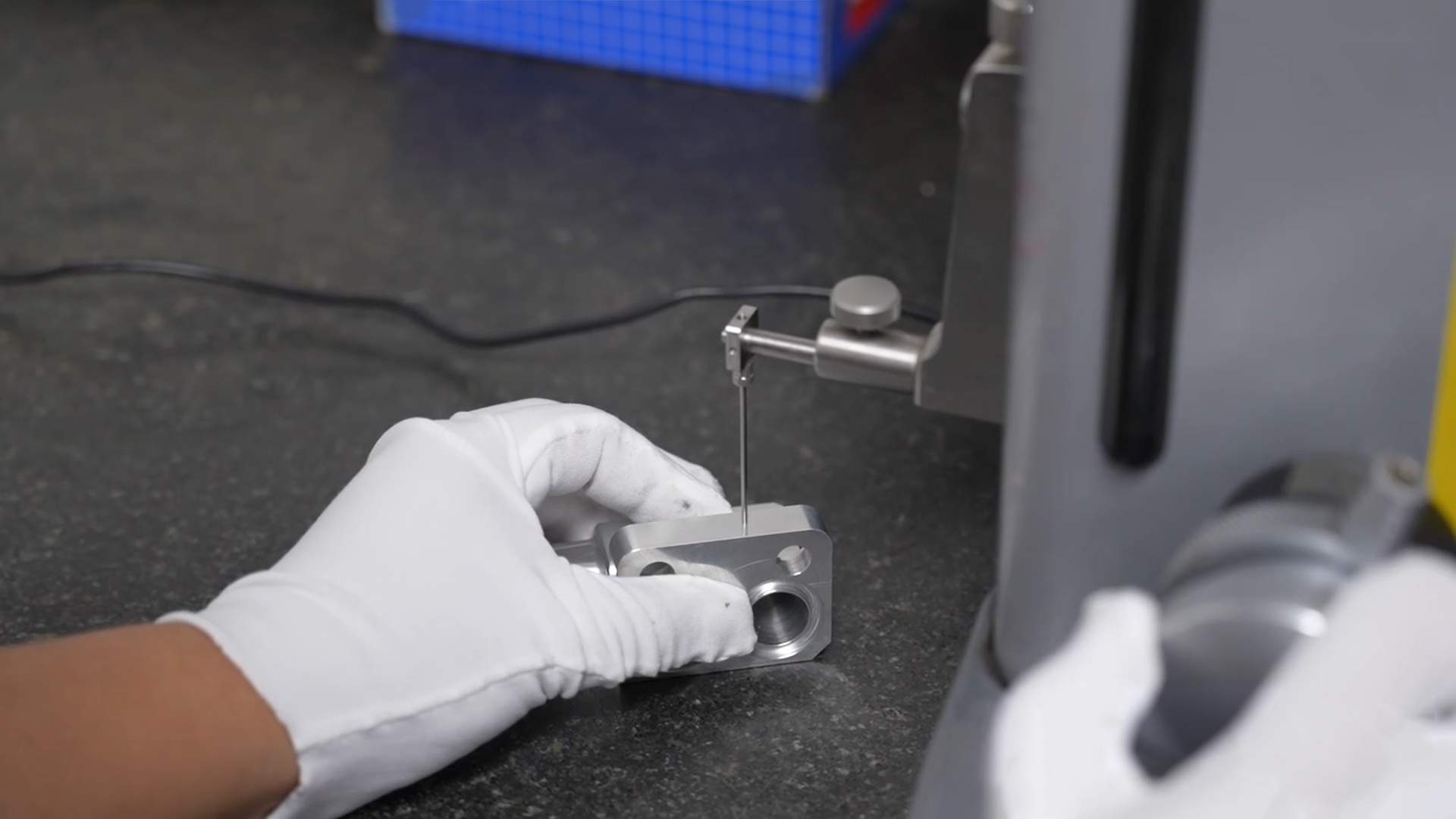
FROM PROTOTYPE TO PRODUCTION
Schedule is reviewed after the flat pattern, material, thickness, bend sequence, joining, finish and inspection scope are confirmed. No universal sheet-metal lead time is published.
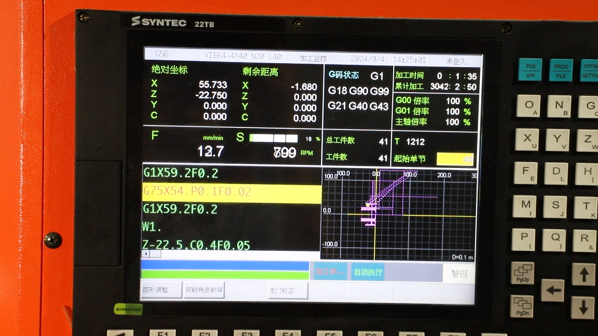
Validate the formed geometry, bend access, joining sequence and finish zones before the delivery plan is fixed
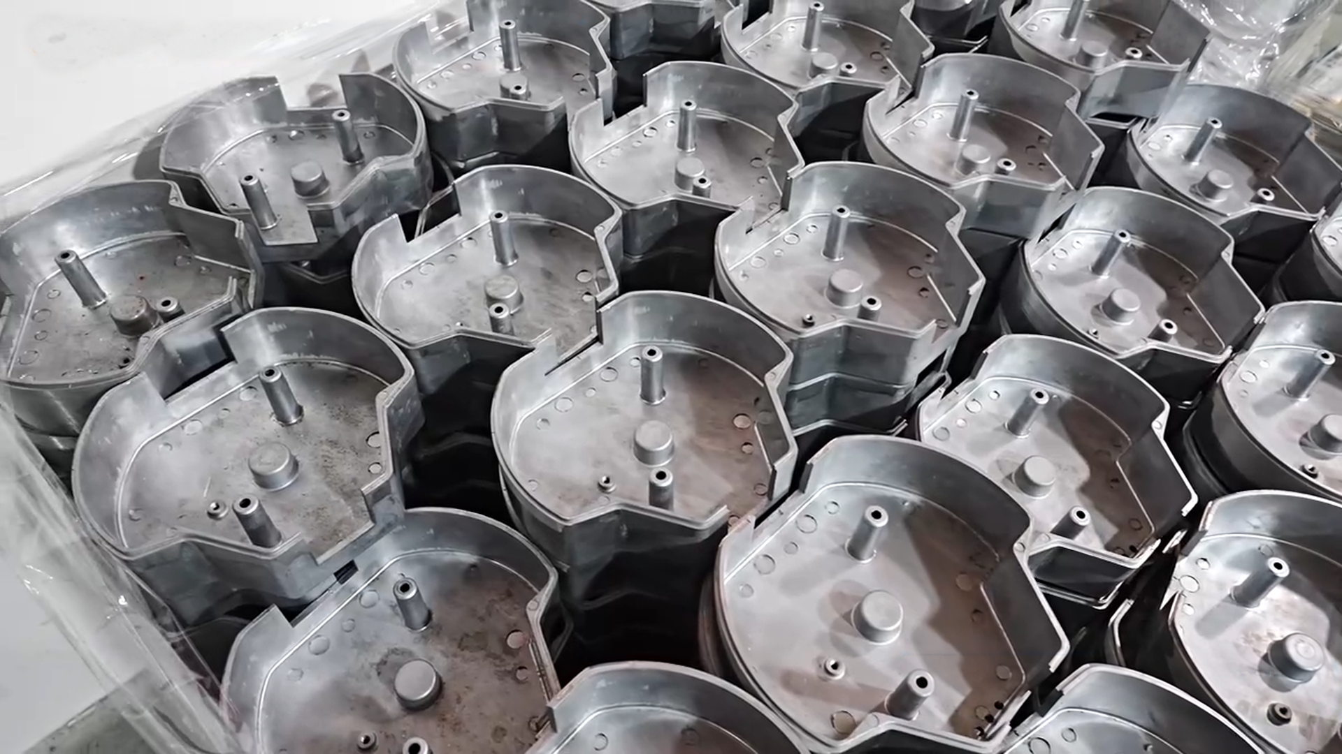
Plan material, hardware, secondary operations and inspection around the approved formed part
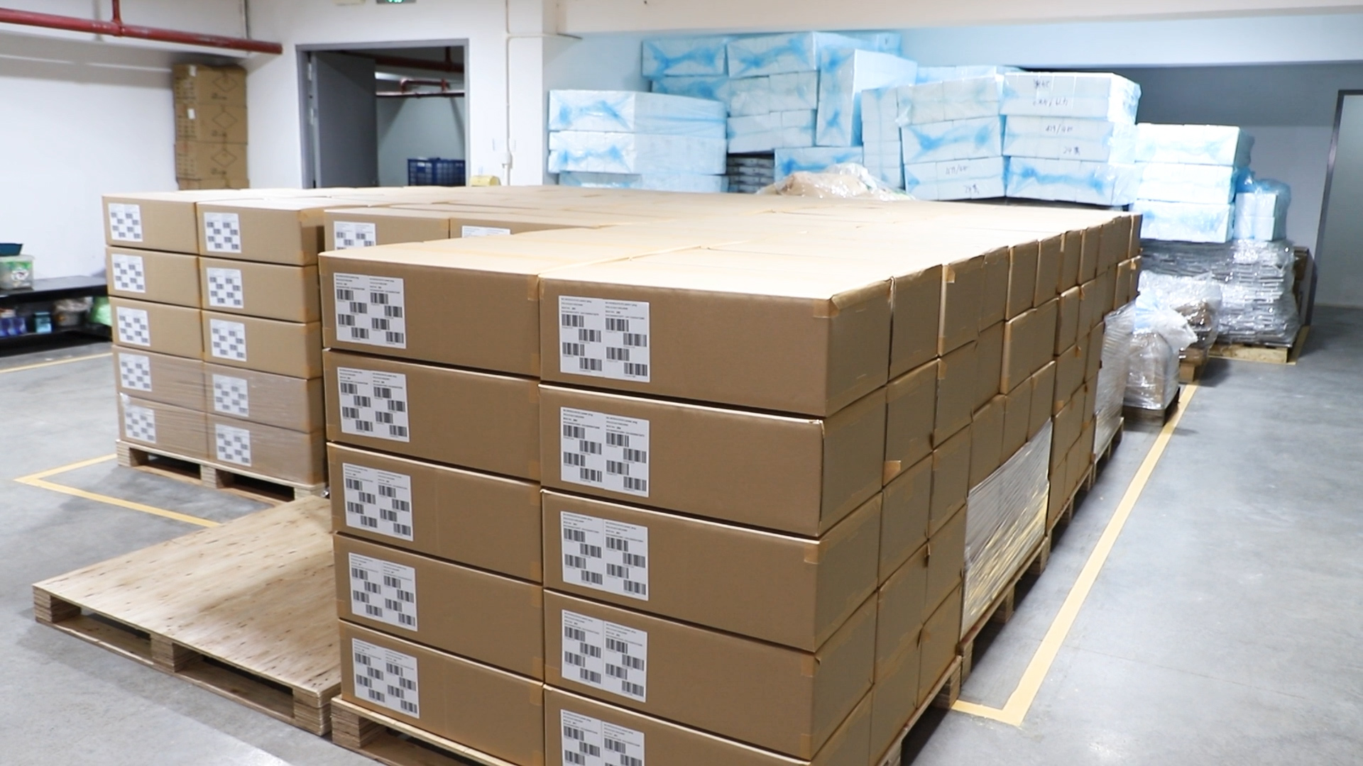
Review quantity, process sequence, finish, packaging and drawing-defined inspection requirements before scheduling
FREQUENTLY ASKED QUESTIONS